Saturday 14 December 2013

Interior prep

After recovering from the roll over I started the interior prep prior to fit out.

First off I put extra braces on the cradle back at an angle to give extra support.  I'll take a photo in a later post, just to stop any movement.   Then I filled between the floor stinger and hull with epoxy.  There were a few places where screws were visible so I thickened some epoxy (thicker down the back near the transom where the slope of the floor was greater) and poured it in.  

Next I removed the cross pieces of the roll over frame and painted inside forward of frame one and along the sides with three coats of epoxy wet on wet.  I did it with a brush, giving the stingers one coat and the ply hull three and it took hours.  It will also have undercoat/sealer and then paint later on.  Below shows the result on the sides, still some ply without epoxy in this shot.


Below is a close up between frame 10 and the transom.


I then cut back the cradle and the tops of the solid wood on each frame, changed the blades on the electric plane and took off the extra ply above the gunwale stringer.  Below looking forward, really shows the interior now:


And down the back again:


And a shot from the side, doesn't really look much different though:


After cleaning up I cut 100mm wide fibreglass tapes for frames 9, 2 (half bulkhead) and frame 1, put a fillet of epoxy and glue powder down and then the tapes.   Below shows behind frame 9:


After frame 9 I decided to actually cut out the piece where the stinger was rather than epoxying it along the stringer (as you can just make out above).  Below is one of the tapes for frame 1, I still left a little bit of glass to go onto the stringer for strength, just not the whole lot:


Here is frame 1 tape in place:


I put a second layer of epoxy on the tapes to make sure the weave was filled, and at the same time used the brush to cut in the large open spaces of ply yet to be epoxied.  These were filled in with a roller, again three coats wet on wet.  The whole thing looks really shiny and a nice colour.  I am thinking about leaving a few laminated beams visible for effect but we will see.

Below is a shot looking to the transom from about frame 4 after the floor and ply bulkheads/frame epoxy had set:


That's all the prep, I have now started the supports for the cockpit and the forward deck.

Saturday 16 November 2013

Roll over

Consumer Warning
This post goes on a bit, get yourself a coffee.................


With fresh memories of John Welsford's website and their three or four hour rollover I summonsed the tradesman (Dad), gathered some equipment (borrowed some from my brother in law, a lot of dad's and ended up not being enough) and we began.

Day One (about 6 or 7hrs)
First thing to do after prepping everything was to have smoko.  Mum catered the sultana scones, jam and coffee:


I had hired a 1 ton chain hoist, but we decided to use a small 6 ton hydraulic jack and chocks to lift it rather than pulling it from up near the roof on the shed supports.  I was worried about the ability of the uprights to take the load so instead would use the chain hoist to lower once it had passed the tipping point. We also had multiple ratchet cargo straps to the shed on each side to hold it in place.

We began jacking up the boat on the building jig, and when the 8cm or so of travel was reached we used wooden chocks to hold the boat while we lowered the jack and packed it up in the air for the next jacking up.  Below is the lift off, you can see the silver jack under the building jig:


And chocking up, chain hoist just visible in the upper left from the top of the shed to the top of the roll over cradle ready to lower once the boat had gone past the tipping point and was hanging on the chain:


We continued like this taking small increases but felt like we were in control.  It did take much longer than just pulling it over from the other side with the chain hoist, but we liked the slow pace and there was no worry of the concrete floor taking the weight.


Up and up it continued, with me getting more concerned about the angle and finding suitable chocks (see lessons learnt at the end).  We used large pieces of wood both sides clamped vertically to lock it in position and were careful to have it locked in with straps whenever we moved around. Slowed us down, but safer.

Below was the end of the first day, you can see we lowered it onto a piece of hardwood to pivot on the right hand side so we did not have to jack so high.  Also just to the left of the worker is one of the vertical props in hardwood.  So much for 4hrs to roll over!


Day Two (2 or 3 hrs)
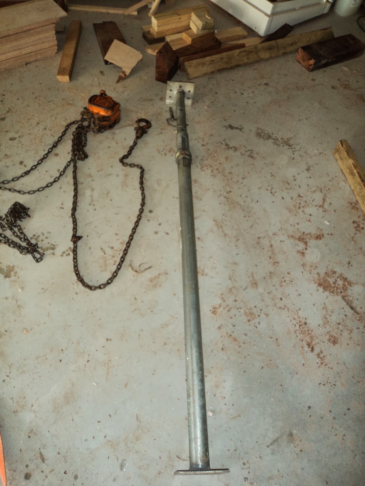
After a break for two days at work and thinking about how it was going I went down and hired two Acro props (see lessons learnt at the end) which I should have done in the first place.  Much safer and stable. Below is a close up of the chain hoist and one of the Acro props which adjust from 1.1 to 1.8m.


With a few hours after work before dark we got stuck into it.  The props were fantastic and sped the whole process up. One would jack up a few centimeters, the other would wind up the props, then repeat until the jack needed to be moved.  The hardest part of the lift had already been done the first day, and it was hanging on the chain in no time.  We still maintained the use of wooden props on the other side so if it went over and we lost control it could only fall a few centimeters before it landed on props.  Did slow down the process as you had to move them up when they got to the floor (see lessons learnt at the end), but safety first!  

Below is on the prop and chain (note orange strap on the left to back up the chain):


And from the other side showing the props clamped to stop it dropping if the chain failed:


We propped both sides to move the attachment point of the chain, the blue cargo strap visible on the bottom of the cradle above and below.  Also note the cargo strap back up to the left and right, dad standing on the feet of the building jig:


Quickly we were on the ground.  Below you can see the right hand side on rollers to move, on the left jacking it up to remove the hardwood we pivoted on:


From the other side showing inside when sitting just on the rollers:


Beers all round!

Day Three (8hrs)

Now we knew what we were doing we grabbed another small hydraulic jack because we removed the building jig (the support holding the frames when it was all upside down) and could only jack from each side of the cradle (see lessons learnt at the end).

We had to move the boat back over the other side of the shed so we could roll it the rest of the way to upright.  My dad had brought with him eight stainless steel rods 12mm in diameter.  I looked at them, I looked at him, I looked at them again.  I was expecting massive metal pipe, told you he was the tradesman. We jacked up slightly and placed them underneath:


Then attached a chain and pulled.  Hardly any effort, just place the ones it had rolled off around in front for it to roll on and keep pulling on the chain.  And you could push on the bow to straighten it up.  I could not believe it worked so well, to the extent that mum, dad and I pushed the boat forward after the roll over was complete without even using the chain block.  Below is moving sideways:


Then it was jacking and propping again and again until it was on the chain:


and quickly down:


Rolled it back in position, we pushed it forward on the rollers after aligning them forward instead of across and took out all the frame cross pieces.

Beers all round.

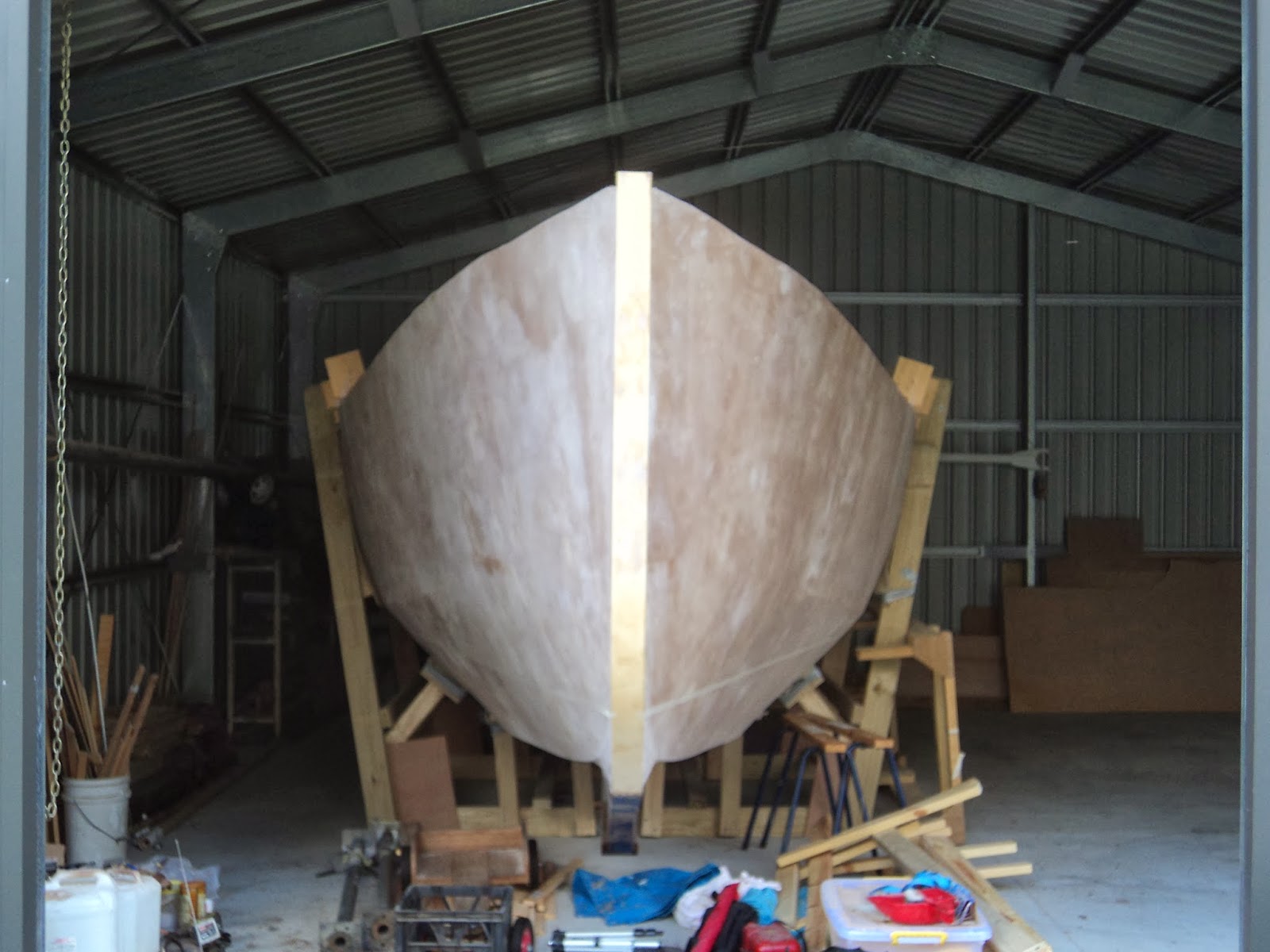
Then photos.  From the front a bit off center to the left:
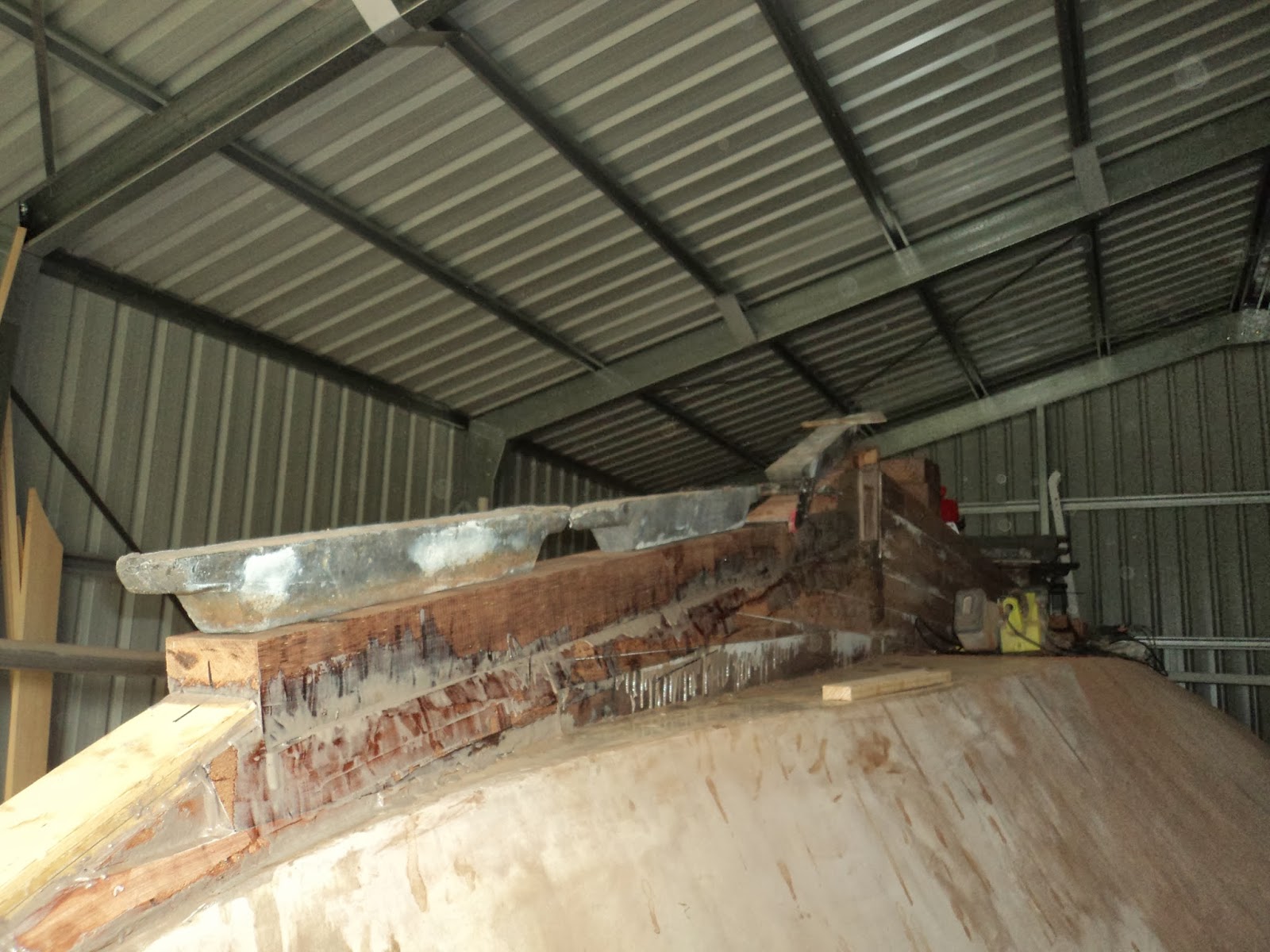

From the side:


 Overhead from aft:


And from the front:


Lessons learnt and what I'd do differently:

  • If you can pull with a chain block from both sides it will be much quicker, but I would still have props for safety in case you want to stop for any reason rather than just leaving it on the chains.
  • Get Acro props, two small and two larger from the start.  Much quicker and safer than chocking with wood once it gets up a bit on the jacks.
  • When you are lowering on the chain and using props on the other side for safety, put the prop a good distance up and put a number of chocks underneath it.  That way you can pull out each of the chocks as the props come down until they reach the floor rather than having to stop and move the props all the time (we figured this out on the final lower, would have saved heaps of time stopping, securing everything and moving them up again).
  • Once the boat is on its side, don't take out the building jig until you have jacked it up a few feet. You have many more options to jack against rather than just the cradle and it is still easy to remove when a couple of feet past vertical.
  • Take your time.  It feels like it is taking forever but if you drop it, worst case onto yourself or someone else, or even onto the ground you will regret trying to save a few hours.
  • Take lots of photos, you will be busy but they help you remember and celebrate the success!


Thursday 14 November 2013

Keel tidy, roll over/support cradle

After running a thick fillet on the keel to hull join, sanding it and doing a couple of quick fairing layers on the bottom it was time to prep for roll over.

Firstly, borrowed a laser level and using the waterline on the transom frame ran the waterline and taped it. So far two people have said it now looks like a boat so heading in the right direction!  From the front:


Looking across at the transom.


Next was to finish drilling up the keel bolt holes from inside.  These are 10mm with four up front in frames 3, 4 and 5 and four down the back in frames 7 and 8.  One of them was a bit too close to the outside of the keel so I am just going to epoxy in the rod to provide sideways support without going into the lead keel.  All the others were good.

Below is a picture of the extension welded onto the drill 500mm to get the up through the keel stack.  Note this was cleaning out the hole from on top after drilling all the way through the cross piece on the frame and the keel.


Once the holes were finished I used 8mm rod as temporary braces which were tightened and then cut off.  These will be replaced when the keel is attached.


The building cradle was then slowly constructed around the hull and across on top of the building jig.  The corners on both sides were reinforced by overlapping 12mm ply with the structural rated timber and through bolting with two 10mm bolts.   Large screws were also placed through the ply into the cross pieces of the cradle wherever the ply touched the wood.


Cross pieces were batten screwed (75mm long in multiples) in at the pivot points, and also between the second pivot point and both sides of the keel.


The cross pieces were also screwed down onto a piece that was screwed into frame 6 as well as the building jig.


Below shows the hull braces between the gunwhale area and the top chine.  With the upright touching the hull, and shorter pieces above and below this meant three points of contact against the hull on this chine.


Below is a side on shot showing the cross braces (two each side on the uprights and four along parallel with the keel.  In addition you can see the braces down onto the bottom of the hull front and rear between the keel outside of the bottom, and against the bottom chine.


Final shot is looking from the front, note the pale masking tape showing the waterline.


Next, roll over.

Monday 28 October 2013

Keel complete (some tidy up to go)

Once the last layer epoxy/glue had set the final steps could get underway.  First off was to fit a capping piece on the end of the keel where the rudder will attach.  A piece of hardwood 60mm wide was clamped and glued into place with the join well covered:


Once that was in place I sourced some hardwood tongue and groove floorboards 20mm thick which when each side was planed to square were exactly the right width.  After a bit of a plane of the keel I trimmed them to the shape:


And stuck them on top with a thick layer of epoxy/glue:


Then it was time to cap the front slope of the keel.  First step was to mark 50mm each side of the centre on the existing wood and plane each side of the keel so it sloped from 150mm wide to 100mm   This left me with a top surface which I put a cut down piece of keel wood (75mm high) onto.

The aft end of this piece meets an end cap on the remainder of the keel which also widens it back out to 150mm.  At the same time I got two pieces of wood and angled them up so they finished where the lead keel will start.

Below shows the cap piece being glued in place, the rear most lead ingot shows the slope up and just to the right of it you can make out the angle to meet the other 150mm wide wood.


Once dry I marked an angle from the stem cap back 600mm to the top surface and planed the front cap piece down.  The final step was to fill some holes between the keel and hull where I didn't quite get the curve right.

After jamming in as much epoxy/glue powder as I could I lay a thick fillet along the join and used a 90mm diameter PVC pipe wrapped in cling wrap as a tool to pull along the fillet to get a nice curve.  Quickly lay on a 100mm wide fibreglass strip and wet it out.  Below shows the result:


As you can see from above and below I then rolled on three coats of epoxy wet on wet over the entire keel including the top.  Below is looking down the keel, you can now see the planed down front cap and the ski jumps which will hopefully help the keel ride up over whatever I hit!


Final shot below shows the worm shoe in place and everything epoxied.  I planed some of the wood off the end of the keel in front of where the propeller goes above and below the shaft line to help improve water flow:


Final steps for the keel are to fillet the remainder of the keel/hull joins with sanding/filler powder and then fair the bottom surface out to the hull curves.  I probably will not have an entry just for that but will include them in the next one which I am excited about - the roller over and support cradle to stand this thing right way up.

Monday 14 October 2013

Keel stack finished

The stacking of keel timbers continued and they are now all in place waiting for the epoxy/glue to set on the final layer.

First off was to drill and position the galvanized threaded rod through the hardwood cross piece in frame two and up through the keel.  After drilling up from inside each end was countersunk using a 22mm spade bit.


I measured the length using a piece of small rod and cut it:


Then tightened it in place.  This one is permanently epoxied into the keel and will have a cover piece above it on the keel.


Below is layer four of the level pieces, this one extends toward the keel.


The last 320mm is tapered from 150mm wide to 70mm to assist with water flow onto the rudder.  Below shot is looking from underneath, 150mm wide just below the lower clamp:


Layer four aft piece in place, looking along towards the transom:


And from the transom looking forward:


The final layers in place, 5 in total at the front.  Note the lead ingots (25kg each) helping to hold the wood down:


Seven layers at the back.  The top two at the transom only go forward 1540mm to allow for the end cap which will be positioned to line up with the transom (18mm thick).  In front of that will be a lead keel:


Looking forward:


Next steps will be:

  • tidy up the keel using an electric plane to get rid of the excess glue, 
  • fill gaps and fibreglass tape the hull/keel join,
  • fit the caps on the front(which will also require a taper) and rear, and
  • fit a worm shoe on the top of the last rear layer.